2012/07/31

Yoke Yoke Yoke - Yokin' it Up!

Yesterday we cut and dry-fit the main cross beam and yoke assembly.  When I arrived today, Sean had fitted it up with this combination of clamps and jigs:

This arrangement brought all three pieces of oak into proper alignment.  We used it for pre-drilling and setting the 2" wood screws from this side. Once that task was accomplished we flipped it around and repeated the process, but with counter-bores designed to receive oak plugs.

View from the aft side, which will be concealed:

View from the forward side, which will be exposed:

Detail of the plugged forward side:


The balance of the day's work was aimed at the galley partition.  The main sheet of plywood was cut yesterday, but today we needed to cut an extension (48 inches to 51-1/2 inches)  Further, we needed to cut the yoke on the forward side of the partition that will receive ribs, and the aft board that will consist of the galley hinge mounting point.

The finished pieces are shown below:


The plywood piece shown will extend the 48" plywood partition to 51.5".  The solid, non-notched oak piece will be the aft-of-partition galley hinge mount.  The notched piece of oak on the right will be the rib yoke forward of the galley partition.  The notched piece on the left will be mounted at the front of the platform to receive the ribs.

Next step:  Build up the galley partition, fit the outside ribs to the wall structures.


2012/07/30

Progress 7/30

Today was another day of excellent progress.  We:

  • Cut the galley partition
  • Routed a rabbet into the galley partition to receive the galley countertop
  • Sorted through the front rib halves to pick out the two best, to be used as interior ribs
  • Cut the three pieces for the main yoke, which will run from side-to-side in front of the galley partition and receive ribs from the front and the rear
The photos below are of the main yoke, resting on the freshly-cut galley partition:


The yoke consists of three pieces as shown above.  The main beam is the center piece.  It acts as a flange that will run through both walls and be bolted into them.  On either side of that main beam is a yoke, notched to receive the various ribs, which will be interrupted at the yoke.  The tops of the three boards are beveled to match the curvature of the roof where the yoke will be installed.

This is a closeup of the port side end.  The trailer front is to the left.  The front rib that is attached to the port wall will key into the notch on the left, while the short rib that runs between the yoke and the galley opening will key into the notch on the right.  The rib sections in question will only be as thick as the notch shown.  The balance of the main beam will protrude through the wall in the cutout seen in the photos of the walls in the previous post.

 
This photo shows the notches to receive one of the interior ribs.  Note that the two yokes and the main beam have not yet been aligned vertically in this shot.

This is the starboard end of the assembly.

This yoke assembly will be a key component in the overall structure of the cabin, working with the galley partition to provide lateral rigidity.  The next step is to pre-drill for the screws that will unite the three pieces, then glue and affix them together with screws.

2012/07/29

Both Sides Receive First Coat of Polyurethane!

Today the trailer port side was moved onto the trailer bed after the bed was covered with rosin paper (typically used in construction to provide a slip between a hardwood floor and the subfloor.)  In this case we simply wanted to protect the deck from what we might place upon it, as in one of the sides.

The starboard side was placed on the work table, where we installed the necessary additional backers.  We then flipped it over and cut out the door and window openings, as well as the channel for the yoke header.

Both sides were sanded with 150 grit paper, and given a first coat of polyurethane.

The port side wall is on the trailer, while the starboard is on the work table:


Tomorrow we will approach the galley partition, the main rib yoke, and getting the platform coated with polyurethane.


2012/07/28

Side Prep

The next step in the process is to get each side properly prepped to be mounted onto the platform.  To do this, some additional "backers" were required in the side wall:


Above is the horizontal backer for the galley counter top cleat, added today.


 Above is the port side provision for a shore connection.

Next we cut out the window and door openings.  A 6" hole saw was used for the corners, while the sides were cut with a router and a flush trim bit.

 
The trim rings are interior, which matches with the image above,since this is the port side interior wall.  The view below shows the installed window and door, assuming the starboard side:


The hole in the foreground is for the shore connection, which will actually penetrate the interior wall.

The slot shown below will receive the 4/4 oak crossmember, to which the rib yokes will be attached (and run between the inner wall surfaces.)


The next step for this side is to sand and apply a sealer coat of polyurethane.


2012/07/27

Side Wall Consistency and Refinement

With the platform complete, our attention turned to the side walls.  The first task was to affix them to each other and, using a special flush trim bit, trim them to each other to assure a consistent profile curve.  

To accomplish this we screwed the two sides to each other.  I used a bit from Rockler, that is a 2" long, 1/2" shank carbide cutter with both top and bottom bearings of differing diameters, to trim the top side to the bottom side (where the top side extended beyond the bottom with a bottom bearing the same size as the cutter.)  Next, we flipped the assembly and repeated the process.

Next we removed the starboard side and left the port side on the table.  We added some cleats aft for the galley counter top:


Next we added some cleats forward for the electrical cavity.  Part of this task for the port side was to accommodate the shore power connector.


The mark above is the centerline of the shore power connector.  A reference hole has been driven through the inside plywood to indicate the center position of the connector for future reference.
 
After all such details are located we will flip the side and rout open the door and window, prepare the side to receive the oak rib yoke assembly, and pre-drill the holes through the sills for the screws that will attach the sides to the platform.


2012/07/26

A Milestone Day

Today was definitely a milestone day.  To start, we added the sides to the party tent under which the trailer is being assembled in order to protect the trailer from rain.  Next, we leveled the trailer so that the basic construction is conducted from a position of level.

Next, we cemented the ell for the clearance light feed:


We will tap into the right rear tail light and connect to the clearance light feed, route it to the rear inside plastic sub-ducting, then feed it up into this fitting and then into the open end of the wye seen forward, and finally, up into a cavity inside the hatch.  From there the clearance light feed will go to the front and rear left and right side clearance lights.

The view below shows the trailer base ready for the deck:


We started affixing the deck plywood from the front:

Next we applied the center and the aft pieces.  Each piece was glued down and screwed to the 2x6 frame.  The pieces were joined with biscuits.

With the deck fully attached, the next steps are to fair the two sides to each other (to assure a common profile), trim the rear portions of the laminations to fit the trailer, prepare the galley partition, then affix one side, the galley partition, then the other side.

Stay tuned!
 

2012/07/24

Electrical Routing, and the Deck

Today we worked on the conduit that will carry the wiring between the battery (tongue) box and the cavity in the front of the cab where all the connections will be made, and the conduit that will carry both 120v and 12v distribution from the front to the rear.

Refer back to the previous post to see the connection between the battery box and the trailer body.  Sean made some washers to help flatten the gaskets against the aluminum, in particular the diamond plate of the battery box.  We permanently affixed the connection at the trailer's front edge and installed an ell rather than the sweep shown previously.  

Next we ran a conduit along the starboard side from a point just behind the galley partition to the front, then laterally to the same general area as the tongue box conduit.  This pipe will carry some 3/8" "sub-ducting" or corrugated plastic tubing, within which we will run either the 120v or the 12v wires back to the galley partition.


In the view above you see the longitudinal pipe terminating in a wye - a pluming term for a y-shaped part.  A "street" 45 turns the run to the vertical.  This penetration will be just behind the galley partition.  Three sub-ducts will be installed - one for AC, one for DC, and one spare.  The open end of the wye will permit convenient access as required, and will accommodate a feed from the trailer rear for a clearance light circuit.

This view shows the head end of the trailer and the two turns to the vertical that will penetrate up into the interior wiring cavity.  Again, note that for the battery box connection we have switched to a standard ell from the previously shown sweep.  The sweep has been deployed on the aftward run .


This view shows the front two platform panels with holes fit into them for the penetrations.

Tomorrow we will pre-drill through the plywood then screw it to the structure, completing the platform.

2012/07/22

Future Preview

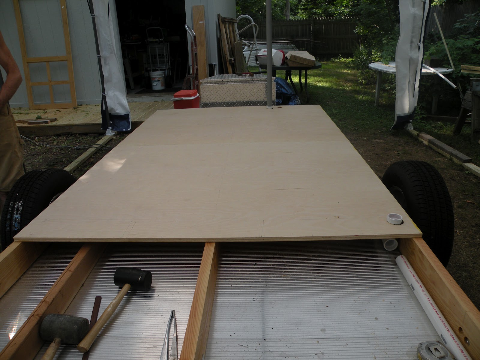
During a pause in construction I offer the following preview of the future of this blog.

Note:  Click on an image to enlarge.

Little Blue Heron


I love the droplet of water between the points of the beak.  The bird had just attempted to catch a fish, unsuccessfully.

Platanthera Ciliaris (aka Yellow Fringed Orchid) (aka Cheese Whiz Orchid)


Affectionately known as the Cheese Whiz Orchid, owing to its color, this fringed orchid is interesting for its fine fringes.  I also love the two "fangs" you can see on the roof of the "mouth."
 

Red Tail Hawk Close Up


What can I say about this?  He was sitting in a tree above me and being very cooperative. 

Bauer Park, Madison CT, Winter, HDR


This was my first attempt at an HDR photo.  HDR stands for High Dynamic Range.  It is created by combining multiple images at different exposures in order to bring out the highlights and the shadows equally.  Imagine you are standing just outside a short tunnel. The inside of the tunnel is relatively dark, while the "light at the end of the tunnel" is relatively bright.  The human eye can resolve these differences, but it is very difficult photographically to do the same.  HDR combines the differing exposures to preserve the detail in the dark without the light being washed out.  The above photo does this while accenting the blue of the sky, both directly and reflected in the still water. 

Neighborhood Merlin

 
 This merlin was hanging out in our neighborhood in early March.  I love the pose.

Red Belly Woodpecker


I just can't get enough of this bird.  He was posing so nicely ...

Tufted Titmouse

What can I say?  These little things are just too cute for words.

A Very Primitive Panorama


This was my first attempt at a panorama.  Taken in 2005 at the Grand Canyon, it is composed of six frames stitched together in Photoshop.  One of the goals of the Teardrop project is to revisit the Grand Canyon and do justice to it.

While this photo spans probably 160 degrees, it is limited by its horizontality, and by the fact that I was using a polarizer for the shots.  If you look closely you'll see the difference in sky color owing to the differing angles from the sun.  There is even a visible vertical seam just to the right of the hiker that stepped into two of my frames.  Further, the horizon is distorted by the limits of my (then current) equipment.


The equipment has been improved significantly since this photo.  The Nikon 300S body is supplemented with a Nikkor 14-24 f/2.8, a Nikkor 24-70 f/2.8, a Micro Nikkor 105mm f/2.8, a Nikkor 70-200 f/2.8, a Nikkor 200-400 f/4, a Nikkor 24mm f/3.5 Tilt Shift, and a pair of teleconverters.  All of this is supported by a Gitzo carbon-fiber tripod with a Really Right Stuff ball head and various other RRS components.  I also have a Wemberly gimbal head for tracking birds.  This lineup will allow me to accomplish just about any shot I can imagine.

Moose Peterson has written about panoramas that not only span several images horizontally but three or more vertically.  In particular he writes about using a tilt-shift lens for ultimate depth of field.  I'm intrigued!  And, combine that with HDR, well, the results could be spectacular.

But, you need to be where the landscape will support the technique to render the artistic result.  And, thus, the main purpose of the teardrop is revealed - to get me where the opportunities exist.


2012/07/19

Connecting the Battery Box; Power Sourcing

Having the batteries in the tongue box and the Xantrex converter in the front of the trailer requires three 2/0 wires between the two locations.  To accomplish this we are connecting the box to the trailer with a 1-1/2" conduit and a "pattern sweep" to turn the cables up into the cavity where the Xantrex converter will be mounted.

First, we had to drill a hole in the tongue box, which required that we unbolt it from the frame.  See the hole below:


Next we drilled a hole through the front skirt of the trailer and the 2x6 inside frame member:

Here is a view of the conduit connector fitted into the tongue box; note that the final fitting will include a rubber washer to seal against the diamond plate:


This is a view of the fitting through the trailer skirt, which will also have a rubber washer in the final form.  A length of PVC conduit will connect the tongue box with the trailer.

Finally, once inside the trailer, a pattern sweep will lead the cables upward into the Xantrex cavity.


The top of the sweep will be extended with a coupler and a length of pipe as needed through the plywood floor of the Xantrex cavity via a bored hole.  It will be held in place with another coupling to fair the end of the run.

The Xantrex converter, to review, will:

  1. Charge the battery (via inversion) when connected to "shore power" 
  2. Provide 120v AC direct from "shore power" when connected
  3. Provide 120v AC converted from the batteries when "shore power" is not present
DC power is always supplied directly from the batteries.  There is also a provision to trickle-charge the batteries from the car's alternator when underway.

The Xantrex has an AC end and a DC end.  The AC end will be oriented to port side where the shore power link will be installed.  The DC end will be to starboard, and that is the side to which the above detailed conduit link will be positioned.

The AC output from the Xantrex will be fed to an AC breaker panel for distribution.  The DC connection to the batteries will be fed to a DC breaker panel for distribution.  A pair of DC meters (voltmeter and ammeter) will be connected to observe the battery status. 


2012/07/18

Lectricals, and Heat

At one point today the temperature readout in my car read 102.  And, it was humid on top of that.  This is just to set expectations.  No, we did no building today.

On the other hand, we've procured the bulk of the electrical stuff we need to proceed.  In short, we have to create a conduit between the tongue (aka battery) box and the main portion of the trailer, and bring that conduit into the cavity where the Xantrex will be mounted and the various distribution panels will exist.  We now have the conduit, the wire and the connectors required.

I managed to find a DC circuit breaker/disconnect on the web, and it is on order.  I also found some 3/8" flexible plastic conduit, also known as sub-ducting, which can be routed around the trailer and carry loose wires from the two panels to the terminal devices.

The only critical missing piece is the AC GFCI breaker to sit between shore power and the Xantrex.

Folks, it was just too blooming hot to do anything today.  And the "severe weather" we were promised has not materialized for my location - just a few sprinkles.  I feel robbed.

2012/07/16

Ides Plus One

Well, not so fast.

Today was spent going over the high-level electrical design and component list.  With Sean's collaboration, the main wiring center was relocated from just in front of the galley partition to the planned cabinet in the front of the cabin.

As it turns out, the Xantrex converter wants the wire length between the batteries and the converter to be no more than five feet.  The batteries are in the tongue box.  The planned location required a 20' cable run - far more than five feet.

While I might have been willing to accept the reduced converter performance given the added distance from the batteries, there is no question that the new location, within the five foot specification - will be superior, not to mention a lot cheaper given the shorter run of three strands of 2/0 copper.

The revised bill of materials has been finalized.  Tomorrow, the plan goes, brings the visit to the electrical supply house.


2012/07/15

Update on the Ides of July

Ides of July?  Whatever.  Today was spent researching and acquiring the batteries for the trailer (a pair of AutoCraft 6 volt golf cart batteries) and creating a detailed list of other required elements for the electrical system.  Tomorrow I will visit a local electrical supply house to obtain the required footage of 2/0 cable and associated connectors, switches, fuses and such.


2012/07/14

The Trailer Has Been Ransomed

Trailer Depot finished up the latest modifications to the trailer today and it was returned to shelter under the party tent.  I'd like to acknowledge Paul and his people in the Service Department for their ideas, dedicated work and quick turn-around.  Thanks!


I made note of the three modifications being performed in yesterday's post.  Here is the tongue box:


The box will contain the two 6-volt golf cart batteries (connected in series to yield 12 volts).  A wire will run from there to the converter mounted in a cabinet in the cabin.  A connection will also be made to the 12v line from the connection to the car in order to trickle-charge the battery while underway.

The other two modifications can be seen below:


First, note that the fender is missing.  In order to be able to caulk the joint between the side and the trailer frame the fender had to be removed.  Where it was previously welded on, it now bolts on.


Second, see the new spare tire mount.  The spare will ride behind the axle, elevated and  somewhat inboard of the main tire.


Both photos show the frame structure bolted in place.  Prior to screwing down the platform cover we need to resolve the routing of the main supply between the battery and the converter; to do that, we need a) the batteries and b) the wire and connectors.


Interior


Meanwhile, here is a view of the galley partition looking aft:


The very top thin rectangle represents the main beam (below the ceiling) that will carry the two rib yokes.  Below that are the three electrical panel components - the 120v breaker panel, the 12v breaker panel and the 12v meters.  To the right the converter's position is indicated.  The entire panel will be a drop-down, hinged on the bottom with retainers to prevent a full drop.  The electrical panels will be mounted through this side-to-side panel, and the converter will be mounted inside the cavity created.  All the wiring for the trailer will terminate within this cavity.

Below the electrical chase are two cabinets and two shelves.  The cabinets will be enclosed with custom made white oak tambours.

Below that is a two foot high by one foot deep extension of the main cabin.  The main cabin will have a total of 7' 6" floor space.

Galley Space

This view of the galley shows, from bottom up:


1) The under floor storage running the entire length of the trailer.  To facilitate access I plan to build trays that just fit sidewise and are 2-1/2 or 3 feet deep to slide into the cavities.  I have an extendable boat gaffe that will be used to hook into prepared holes to pull each tray out as required.  The most-unfrequently-used stuff will be stored forward.
2) The areas allocated to the plumbing, the cooler and the portable stove storage.
3) Two tambour-enclosed cabinets on the left, a tambour-enclosed coffee maker (the absolutely most important appliance onboard!) storage in the center, and two drawers and a lifting lid storage on the right.
4) Storage above for paper towels and other such items.


The area just under the stove storage is further flat storage; the floor of the stove storage area will be removable for other future use.  The cooler will sit on a tray with full-extension slides; behind the cooler will be provisions to store six one-pound gas cylinders for the stove.

After we get the platform complete, the walls erected and the interior ribs positioned, a lot of detail work exists before the whole trailer gets enclosed and clad in aluminum.

Please stand by!

2012/07/13

Update Friday the 13th

Unfortunately there isn't much to report.  After the platform was fitted, I took the trailer back to The Trailer Depot for some additional modifications:

1) Add a tongue box to accommodate the batteries
2) Cut the welds holding the fenders on and replace the welds with bolts through the frame.  This was required so that the seam between the aluminum side and the trailer frame can be fully caulked for weatherproofing.  The clearance between the inside of the fender and the cab side prohibited access for caulking.  The only way to accomplish the weatherproofing was to remove the fenders.  It also leaves open the future option of replacing the existing fenders with "cheeks" that serve as fenders as well as providing storage for such items as the spare tire on either side.
3) For now, add a spare tire mount behind the drivers' side axle.

If all goes well, I should be able to ransom the trailer tomorrow.

Meanwhile, the following activities have transpired:

1) Seal the 2x6 platform components and the underside of the plywood panels with polyurethane to inhibit moisture penetration.
2) Refine the design of the galley area.
3) Design the cabin side of the galley partition to include provisions for the electric components and some storage capability.

More soon! 

2012/07/10

The Platform Takes Form

Yesterday we fit the 2x6 structure for the platform.  For various reasons, the members were ripped down to 4-3/4", except for the center member.  We did some fitting, and drilled the holes in the wood that would be used to bolt the platform to the trailer.

Unfortunately, yours truly miscalculated on the height above the deck for the holes, and we were too close to the top edge of the trailer side.  So ... we redrilled new holes today, then carried them through the sides and temporarily bolted the 2x6 members to the trailer.

Here is a detail of the 3/8x2 stainless bolt (typical):

(Note the line of the plywood surface is somewhat distorted by the lens on the point-and-shoot camera in use.)  We used 3/8x2" stainless bolts with flat washers inside and out, and a lock washer inside under the nut.  On the inside, the washers and nuts are countersunk so as to provide no obstruction for the under-deck storage.

(Again, that curvature you see on the plywood is an artifact of the lens.)  That space under the deck will be used to carry various items, including chairs, a table, and potentially a screen room, as well as other items that might be accessed infrequently.  Not to worry, I've already purchased a telescoping boat pole to be able to snag and extract items in the far front.


Here you see the entire platform in place though not fully attached.  The plywood will be glued and screwed down to the 2x6 structure.  Everything wood will be pre-sealed with something akin to spar varnish to inhibit moisture penetration.  The plywood sections (there are three) will be aligned at the seams with biscuits.

We are awaiting a call from Trailer Depot that the material they ordered to mount the tongue box has arrived.  The tongue box will hold  the two 6-volt golf cart batteries that will be the heart of the electrical system.  While the trailer is away getting the box mounted we will seal the wood for the platform.  When the trailer comes back, the platform will be permanently mounted and the plywood attached.

Meanwhile, we will build up the structure for the galley and mount it to the platform.

Then, the walls go up!

2012/07/09

Fender - History?

I've never liked these fenders.  Their angular form doesn't relate to the profile at all.  They're relatively cheap, and they're not as wide as the tires  Bottom line:  they don't fit the design, but I had no say in their form as delivered.

Another issue is where to stow the spare tire.  The trailer came with a bracket to store it horizontally on the tongue, but I want to place a tongue box there to contain the batteries.  There is no space to store the spare underneath the trailer, and no space on the tongue, so where does it go?

It may involve a minor re-design. 

The current (stock) fenders present some challenges:

  1. How to adhere the plywood to the side structure behind the fender structure when the exterior plywood is applied
  2. How to adhere the aluminum exterior to the plywood behind the fender strucre, and
  3. How to caulk the area where vertical meets horizontal and the access is limited to 1/4" +/-.
There is no good answer to any of the above points.  And thus was borne the desire to remove the existing fenders and discard them.  But, removing and discarding the existing fenders would require construction of replacements.

"Aha!"  You say.  "An opportunity manufactured."  

Well, yes.  After all:

  1. The existing fenders are not acceptable visually or mechanically
  2. Finding a place to store the spare tire has been an ongoing struggle
  3. We might well create replacement fenders that take the form of cabinets, or storage areas, on the cheeks of the trailer behind the axle wherein a spare could be stored, and that reflect the overall profile of the teardrop.  
"Whoa!" You say.  "Solve a practical and aesthetic problem at the same time?"


Well, Yes.


Stay tuned.

2012/07/08

Ongoing Doldrums

Today continued the heat/humidity that has made it so difficult to get anything meaningful accomplished recently.  

However, when my wife, Sam "Eleanor" Saulys, called and asked if she could "drop by," we had to accommodate.

We had already put the trailer under cover; we propped one of the sides on the trailer and added the trim rings for the door and window.

Had you been able to view the backside of this, it would have immediately taken you (as it did me) to the movie "Blazing Saddles" where the entire town of Rock Ridge is replicated on the open plain as a series of propped up facades to deceive Hedley Lamar's henchmen into thinking it was the actual town.  What you see below was propped up by a piece of furring stip and a couple of clamps:

 As you can see, she just made it into the photo.  Note also that the trim rings for the door and window are in place to give a sense of final form.

2012/07/06

New Shelter

We decided that it would be good to have additional under-cover space to assemble the trailer.  So, today we erected this "party tent" to provide that space.

 This will permit us to keep our workshop setup under the previous structure while having the trailer under cover.

2012/07/05

Finally!

We didn't accomplish much today for various reasons (my own) but we did manage to prop one of the sides up on the trailer.  Looky here:

Now, technically you're seeing the inside of the right side wall propped on the left side of the trailer, and it isn't perfectly positioned because we haven't yet trimmed the rear of the rib, and the door and window haven't been cut out, but you get the idea.

This was a really cool experience for us, and it validated the overall design "look and feel."  I just love this shape!

Our next steps are to erect a shelter under which the trailer will be positioned, wheels off, set on low blocks so as to lower the overall working height.  Then we will build the platform (represented in the above photo by the single 2x6 visible under the wall), the galley structure, and the header/yoke for the inner ribs, then assemble the above and the inner ribs and other structural components.

Here are some additional views: