2012/10/29

Hatch, Storm Prep

We managed a little more progress on the hatch before turning our attention to storm preparations.


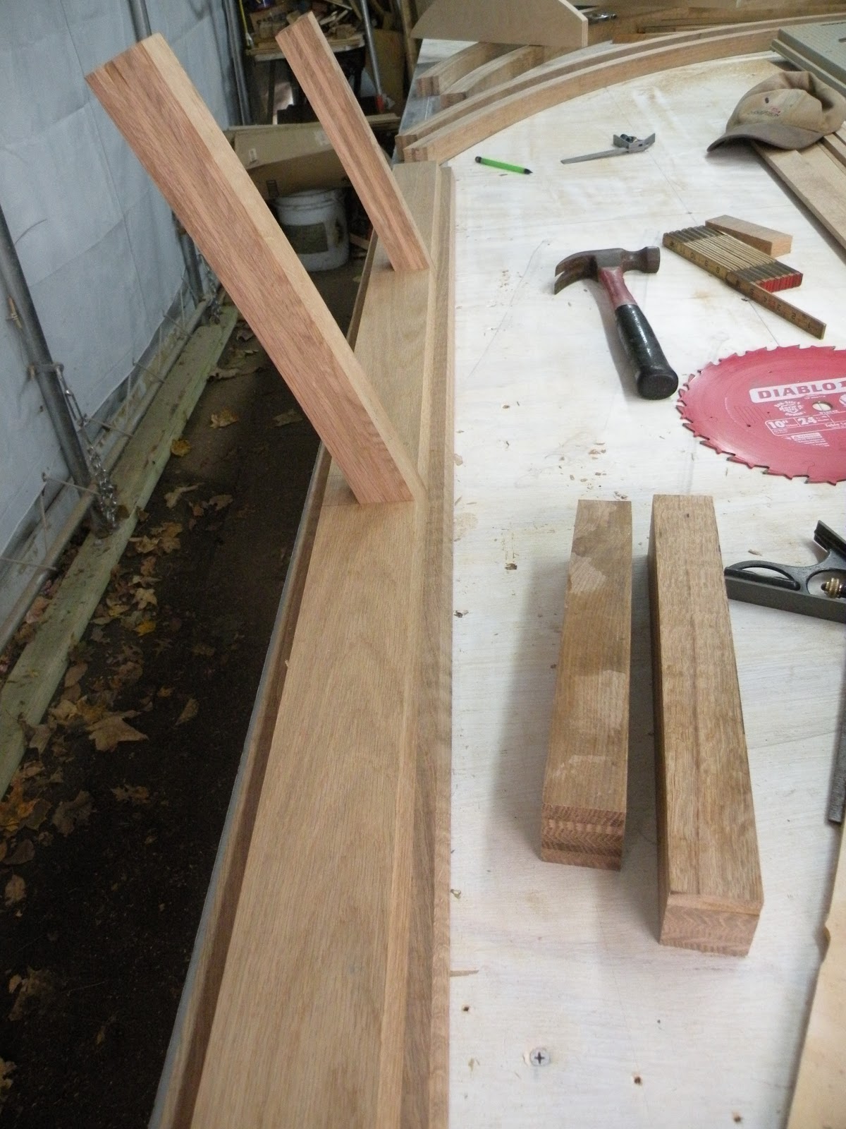
Above is the detail of the rib connecting to the top of the hatch.  Note that the rib has been rabbeted to accept the beadboard and the 1/8" Baltic Birch plywood cover, while the top of the hatch is built up from two pieces to provide a similar detail.

Below see a sample of the beadboard fitting into the notch. 


Note that no permanent assembly has occurred in these shots, and some fitting remains to be done.

Meanwhile, Hurricane Sandy was approaching, and given that our area is scheduled to receive 90+ mph winds, we decided to remove the cover from the "party tent" that had been covering the trailer, and to cover the trailer separately.


It seems so bare without the tent.  Also, with the tent cover removed, the trailer itself seemed suddenly much smaller.

Wish us well - and recognize that it will take some time to get back to work after the storm passes, assuming the presence of electricity.

2012/10/26

Framing the Hatch

The framing of the hatch began with fitting the outside ribs to the trailer opening.


Here the left side is seen clamped tight to the left side of the trailer.  In actuality there will be a 1/4" gap between the two parts to allow for closing the hatch without binding between the sides.


Shown above is the top header, a two-layer piece where the inner piece runs between the outside ribs and is notched to receive the interior ribs.

Below is a detail showing an interior rib joining the bottom assembly.  Note:  the illusion here is that the bottom piece is beveled on the edge closest to the edge of the table; in fact, is is not.  It is a full 13/16" thick and square edged.


The assembled top and bottom components - the bottom is to the left, the top to the right - showing the two layers of each and the relationships.  For the top piece on the right (up is to the right), the two bevels are offset by the thickness of the beadboard plus the 1/8" plywood sheathing (see right edge.)  The bottom piece on the left (up is to the left) shows that the inner piece, which traces the curve of the profile, terminates about 1.5" above the bottom edge of the part.  This allows the bottom edge to seal against the trailer's bed.


Below the parts are dry-assembled.  The inner ribs have not yet been properly trimmed to length.

 
The hatch top is to the bottom/right of the photo, and the hatch bottom to the top.

The next steps are to cut the rabbets in the outer ribs to receive the sheathing, then do a preliminary assemblage of the outer ribs and the top/bottom parts so they can be placed on the trailer to assure proper fit.
 

2012/10/23

Milling the "Beadboard" for the Hatch

The inside of the hatch will be exposed - that is, the ribs will be covered on the outside but not the inside, leaving the ribs visible.  The outer covering will consist of 3/8" thick by about 3/4" wide tongue-and-groove boards with quarter round noses.  Originally it was to be traditional beadboard, but since the board width needed to be narrow in order to conform to the curve of the hatch, the additional grove was eliminated.  On top of the beadboard we will add a layer of 1/8" Baltic Birch plywood.

We started with 8/4 white oak nominally dressed to 1-13/16".

From this we sliced 3/8" pieces that were subsequently ripped in half.  The first milling step was to create the groove and nose on that side, followed by milling the tongue side.

Here is the setup on the router table creating the tongue side:


And a detail of the cutter head:


Finally, the stack of completed boards:


Reminder:  you may click on any image in the post to view all images in the post in a larger format.
  

2012/10/18

Recent Progress

Our priority is the hatch.  To that end we need to mill over 600 lf of the modified beadboard for the hatch covering.

We start with 8/4 white oak and saw it to 3/8" thickness.


Next we will sand one surface of each board before splitting them in two to approximately 3/8 x 3/4".  The sanded, split boards will then be milled with a tongue on one side and a groove on the other, both with a quarter circle detail.

Meanwhile, we surfaced the four hatch ribs on both sides.


2012/10/13

Hatch Center Ribs and More

The last post addressed the hatch outer ribs.  Since then we have molded and removed the first center rib, and placed the second center rib in the mold.


Since the center ribs are 1/2" smaller than the outside ribs as measured from the outer surface, we a) added a 1/4" piece outside the metal bands and b) added 1/4" pieces of oak beyond that to make up the 1/2" required.

As of today, the first interior rib has been removed from the mold and the second rib built up.  We expect to remove it in two days.

Meanwhile, work has proceeded on the electrical cavity cover and its vents, and holes  for the speakers.


Visible above are the vents and the speaker holes.  The top cover of the electrical cavity will need to vent heat created by the Xantrex.  It will additionally hold the speakers inside the cabin for the radio/mp3 player.


Above is a detail view of the vents at the center of the cavity cover.

The vents are made of sapele, and mounted on white oak.

Below is the electrical cavity cover with the first coat of urethane.


I love the contrast between the white oak and the sapele (mahogany) coloration.  Note that the circular holes are for speakers that will be mounted in the cabin.

Additionally, the two lower doors on the electrical cavity received their first coat of urethane.


We recently tackled the tongue box, which will hold the two batteries, the DC circuit breaker, and the alternator interface (to charge the batteries while underway.)

In order to gauge positioning, we created two foam "batteries."


Next we added a mounting rail to the top rear of the box to mount the DC circuit breaker and the alternator interface.

  
The device on the left is the circuit breaker, and the device at center of the photo is the alternator interface.  The plywood part in the bottom of the battery box will eventually have cleats attached to locate the batteries and prevent them from moving around inside the box.

A second coat of urethane was applied to the electrical cavity cover and lower doors.


Vent detail:


Meanwhile, all four hatch ribs are complete.  The next step is to surface them, then build up the hatch infrastructure.

Note that the table has been stripped of all mold components and prepared for pure flat-table use.


2012/10/10

Comparison Shopping

Just for fun, have a look at a couple of options to my teardrop:

This one is from Orvis. Not bad, really, but a bit overpriced for what you get.

This one is from Neiman Marcus.   But they've got it all wrong ... the hatch is on the front, and you cannot get into the trailer unless the pullout is open.  Still, talk about over the top - only two will be made, and with a price to match.

I wonder who is manufacturing these things?  Anyone know?

Hatch Ribs, Hatch Skin, Electrical Progress

In the previous post the first hatch rib had been placed in the mold.  Two days ago we removed it from the mold and placed the second rib.


Here you see both outside ribs.  These are both 8-ply, making them 2" thick.  They will have a rabbet created around the outside edge on one side that will be 1/2" deep to receive the skin.  Next we will create two center ribs 1-1/2" thick to allow for the skin. 

A test was created for the proposed skin, comprised of a layer of 3/8" x 3/4" white oak tongue-and-groove bead board (without the additional beading) and a layer of 1/8" birch plywood on the outside.


For the purpose of the test we didn't bother sanding the saw marks off the inside surface of the slats; this was more a functional test to gauge stiffness and assembly technique.  The two plywood sides were patterned on the sharpest point of the curve.


Here you can see the individual slats with tongue-and-groove detail, and the 1/8" birch applied.

The test revealed several things:

  1. The 1/8" birch ply is necessary to enhance stiffness, although it does not make the hatch rigid.  Therefore we may need to add some lateral bracing inside the hatch.
  2. The milling will be time-consuming, as we will require approximately 140 slats, each 5' long, for about 700 lf.  The process involves ripping a 3/8" slice from 8/4 oak stock, then ripping that slice in two to produce two slats.  Sanding will be necessary on one side to remove saw marks.  Next, the groove edge is milled on the router table, followed by milling the tongue edge.
  3. Assembly requires spreading glue along the length of the tongue on both sides, putting a spot of glue on each rib, placing the slat and nailing with the pneumatic nailer.  Then the glue must be wiped.  Therefore the assembly must be done in such a manner that both sides of the hatch are fully accessible.
  4. Securing the plywood can only be done where it crosses a rib, then at the top and bottom edges of the hatch.  The issue is that we must have a joint since the plywood sheets are 5' and the overall length of the hatch is approximately 7'.  This will necessitate applying the beadboard to the 5' point, then applying the first sheet of plywood, which can now be clamped along the entire edge where it will join the other sheet.  Afterwards, the balance of the beadboard can be applied, followed by the second piece of plywood.  We still have the issue of securing the edge of this piece where it joins the other sheet, but managing this with only one loose edge instead of two will be easier.

Yesterday we pulled a bundle consisting of three plastic sub-ducts, three #10 wires for the rear DC circuits, and a pull string through the conduit from the electrical cavity to the rear of the trailer.  It took two attempts.  The original approach was front-to-rear.  The corrugated sub-duct builds up resistance at every turn in the pipe, and it was too difficult to get it to make the last turn to the vertical.  

The second attempt worked from the rear forward, and was more successful.  Still, after making the last turn to the vertical inside the electrical cavity, it became very difficult to pull.  We got it to an acceptable point and decided to stop there.

In this front-to-rear conduit we have:

  1. Three #10 wires for the DC circuit - positive, negative and chassis ground
  2. Three sub-ducts, one to carry the trailer clearance light circuit, one to carry the speaker wires for the radio/cd/mp3 player, and one spare
Today is an off day, owing to the wet weather.  Recall that the trailer is being built under a "party tent" and the main work table is under a temporary garage structure.  When it rains, the cement floor inside the temporary garage can become flooded, and working with anything electrical while standing in water is ill advised.  Likewise, the saws and router table must be used without any cover, and rain prevents their use.

Sean is continuing the wiring.  My next steps are to sand the vents for the top of the electrical cavity, install them in the cover, and polyurethane that cover and the two lower doors for the electrical cavity.  I have also procured the latches for the four doors and will install them as convenient.  

We can remove the second rib from the mold tomorrow and lay up the first inner one.  When the four ribs are complete, they need to be surfaced and cut to fit, then joined to the top and bottom hatch edges.  I will need to procure the additional 8/4 oak for the beadboard, after which we will need at least a full day if not more to mill it.  Then, finally, the hatch can be fully assembled.

Since the hatch is projected to weigh about 100 pounds, we are thinking it would be advisable to have some kind of spring-loaded assist to lift it.  I don't believe conventional gas struts will be adequate.  If any readers have thoughts on this, or specific parts to suggest, please leave a comment.  And, thank you in advance!


2012/10/07

October is here.

Sad as it is, October is here.  With it comes variable weather and temperatures.

Two days ago we laid up the first of the hatch ribs.  It is still in the mold, assuring that the temperatures at night permit full curing of the glue.  As the temperatures control when we might lay up the next rib, there is no reason to remove the first one from the mold until we are ready to build up the next.

Meanwhile, we constructed a test of the hatch construction - 3/8" x 3/4" beadboard (white oak) on ribs.  The test was small - approximately 24" wide by 10" - but on the steepest part of the curve.  We have added a 1/8" birch plywood outer layer as a test, on which the glue is currently curing.  Without the plywood, the torsional rigidity was weak, a concern for the hatch.  

Today we discussed options for increasing the hatch's resistance to torsional twisting, should they be required.  I believe we have arrived at more than one adequate solution, the choice being 1/4" white oak diagonal cross-members added at the plane of the rib inside surface.

Please stay tuned.
    

2012/10/05

First Hatch Rib

Today we laid up the first hatch rib.


To revisit, we added many more stations for these ribs and, since the critical line is the outside of the curve, used that as the guide.  The metal strips were accounted for when placing the outside blocks.  We kept the inside blocks very close, requiring only very thin shims to apply proper pressure to the plies.

Compared to our original laminations, this was very straightforward and relatively simple to accomplish proper results, even with eight layers.

Note that the vertical element seen in the foreground of this photo was added as a point of leverage used while positioning the glued bundle, which starts at the tight end of the curve.  We drop in the glued bundle, then the metal bundle (which consists of three strips) then apply the shims and push to the outside.


2012/10/02

New Curves

Today we set the blocks for the hatch ribs.  These ribs differ from the originals in significant ways.

The two outside hatch ribs have the same outer profile as the original sides and the same depth, but the ribs we created with the original design profile are already installed in the sides of the trailer (and therefore become "actuals.")  Thus, we need to create additional ribs that conform to those" actual" exterior curves (regardless of the design)

Whereas the original mould blocks were set up such that the interior profile was used as the guide, these blocks are set up to refer to the exterior profile as the design guide, since it is important that the hatch external profile match the trailer external profile.

The center rib profile is 3/8" inside the outer profile, while the original interior ribs were created 1/4" inside the original.  The 3/8" difference relates to the beadboard that will be installed in the hatch area per current design, where the outside will align with the existing perimeter.

Thus, we need to create two new ribs with the existing profile, and one new rib with a 3/8" offset from the existing curve.

Learning from our earlier experience, we decided to install a greater number of stations for the laminations. 


Since we are only interested in the hatch area, the overall curve is length limited appropriately.  

The next step is to laminate an external hatch rib. 

Note that the thin plywood strip attached to the protruding blocks is classified by OSHA as "A Worker Midriff Hemotoma Prevention and Ameloriation Device (AWMHPAD)."

In other words, it will help prevent inadvertent gut gouges that might be incurred while bending over the table (a condition to which your editor is most prone) or in casual passing.

Our fine government at work.


2012/10/01

Recent Progress and Future Prep

Progress has been somewhat slow lately, owing in part to weather, and to critical path items.

The electrical equipment is now mounted and wiring can begin in earnest.  Meanwhile, the cover for the electrical cavity has been created.


Each side of the top will contain a vent to release the heat generated by the Xantrex.  The vents will be made from sapele, a wood very akin to mahogany.  Using a 3/4" round bit, grooves will be routed lengthwise on top and across the vent on the bottom; the intersections of the grooves, which are deeper than half the thickness of the wood, create openings through which air may flow.  Below is a test piece done in oak:


One difference in the final part from the test is that the rib between the longitudinal grooves will be half the size of the groove instead of one third.  Each vent will have three longitudinal grooves, and the ends will be capped with pieces to match the balance of the perimeter.  The perimeter will have the 45 degree bevel seen in other elements of the woodwork.

The next major step is to construct the hatch.  In order to accomplish this we must create three new laminated ribs - two identical (except for left/right handedness) for the outside, and one for the center.  The section shown below illustrates what you would see if you cut through the hatch from side to side (mostly.)

On the left is the port side wall, represented by two sheets of 1/4" baltic birch plywood (the vertical lines) surrounding the eight-layer outer rib (the horizontal lines at top) and the poplar structure below the rib.

The hatch is seen to the right of that, represented by two ribs - the port side rib, which is made up of eight 1/4" layers, and the inner rib, made up of six layers of 1/4" thickness.  The thick white member across the top is 3/8" x 3/4" white oak beadboard running from side to side.  The beadboard is rabbeted into the outer rib, while the inner rib has a profile that conforms to the inside of the beadboard.

If you revisit much older posts you will see that we added plywood on top of the previous molding blocks in order to preserve them should we need to reuse them.  Since the profile of the sides of the hatch must match the outer profile of the original ribs, and since the original ribs were patterned from the inside of the curve, not the outside, we need to use the template Sean made from our original side to create new molding blocks where the outside adheres to the proper curve.

To that end, we stripped the table back down to the original surface.


Next, we placed the template on the table, verified that the profile was slightly different from the original lines on the table, then moved it to a more convenient orientation and traced a new line for the hatch profile.


Above you can see the slight difference between the original design profile and the as-built.

Finally for today's post, clearing the table meant finding places to put all that stuff that had found a home on the 5x12 horizontal surface.  Guess what became a combination material/tool storage and lumber rack?