The end of August has arrived, and originally I thought we'd be much farther along. Alas, we are not, but then again, we are as far as events would permit.
Today the two top doors for the electrical cavity were hinged and mounted, and the parts to mount to the front profile (and thereby provide vertical mounting for electrical components at the front of the cavity) were created. The conflict noted yesterday was resolved in that the entire drilled hole created for the hinges exists within the oak frame and no possible penetration of the exposed face of the 1/2" oak plywood is possible.
Next steps: mount the door drop limiters (that prevent the doors from dropping beyond 90 degrees) and install the front profile spacers and rails to which the equipment will mount.
Visuals will be presented as they are appropriate.
2012/08/31
2012/08/30
Update 8/30
The lack of reportable progress recently is owing to multiple issues, including critical path issues that are yet unresolved.
Prior to proceeding with the installation in the electrical cavity we want to have all details resolved, including the fold-down doors being installed. As of this time, that is the biggest obstacle. While the doors themselves are ready to mount, the hinges I selected for these doors require a hole 11 mm deep, and part of the area where the hole must be drilled is only 1/2" thick. A Forstner bit used to drill the 35 mm diameter hole will therefore penetrate the face of the door, and this isn't acceptable.
An alternative has been mocked up, but won't be available to test until tomorrow.
Meanwhile, Sean has acquired a bandsaw to assist in creating the mountings in the electrical cavity, among many other future tasks and alternative uses, and today was spent assembling the saw.
If there's only one area where we agree (and there are certainly many, many more ...) it is in having the proper tool for the job. A bandsaw is actually long overdue.
Please stay tuned ...
2012/08/28
Visual Progress - No?
Given where we're at, there will be a lack of visual progress for a while.
Today was spent assembling two of the electrical cavity door frames and considering options for the electrical installation.
Please stand by.
Today was spent assembling two of the electrical cavity door frames and considering options for the electrical installation.
Please stand by.
2012/08/26
Progress Today
Today we pushed forward on the electrical design and cavity configuration, and began construction of the cavity doors. The upper doors will fold down 90 degrees or so, and will contain the AC panel, the DC panel and the DC meters panel. They will also hold the Xantrex control and the (forthcoming) Kenwood auto audio system. The lower doors will drop into place and contain whatever items will fit into the space.
2012/08/25
We Have a Cavity, and it is Positively Electric
The electrical cavity in the front of the cabin required building a face frame and mounting a shelf. In this view the Xantrex converter/charger can be seen resting on the shelf created between the face frame and the front of the cabin.
 Next steps: build the cavity doors, begin the wiring.

2012/08/24
Enclosure
The primary activity today was getting the second piece of interior ceiling plywood (1/8" Baltic Birch) installed. While the first piece only had to be fit from side to side, this one added the complexities of length and the vent fan cutout.
We trimmed the piece to width, fit it into the cabin, marked the length, cut to length, fit it again, marked the fan opening, cut the fan opening, fit it again, removed it, applied glue to the ribs and cross-members, then permanently installed the piece.

The above view is inside looking toward the rear.

The above view is from the front outside looking toward the rear.

This view is from the rear outside looking forward.
A section of the ceiling remains to be installed between the main yoke and the galley partition, As we currently have no plywood left-overs that size, and that it does not factor into the electrical wiring, it is not a priority.
The electrical cavity face frame has been sanded and will be fit tomorrow, along with the shelf on which the Xantrex will mount.
2012/08/23
Electric Compartment Preps, and the Fan Curb
Yesterday and today were devoted to a) creating the fan curb and electric compartment face frame, and b) prepping the cabin to receive them.
Here is the electric compartment face frame:

The top of the face frame is to the right.
To review, the electric compartment will be located in the very front of the cabin. It will contain the Xantrex Charger/Controller that a) charges the battery from shore power, and b) creates 120v power from the 12v batteries if no shore power is available. The electric compartment will also contain the shore power feed and circuit breaker, the 120v breaker panel, the 12v breaker panel, the 12v gauge panel, the Xantrex controller front panel, and an AM/FM/CD radio with USB.
 Above is a view of the face frame side, showing the scribe edge that will allow fitting to the contour of the trailer sides.

Above we see the front cabin preparations for the face frame. The bottom cleat and interim shelf cleats are in place, as are the top front and side cleats.
Following are some views of the fan curb. The idea of the curb is that it project above the roof minimally to provide a flat mount for the fan while providing to carry the roof curve for the exterior plywood, and that it project below the inside ceiling in the same manner.

And the view from beneath:

Now that we have the roof penetration built and located, our next step is to cut and install the inner plywood. After that, the face frame will be sanded and installed, after which the electrical installation can begin.
Here is the electric compartment face frame:

The top of the face frame is to the right.
To review, the electric compartment will be located in the very front of the cabin. It will contain the Xantrex Charger/Controller that a) charges the battery from shore power, and b) creates 120v power from the 12v batteries if no shore power is available. The electric compartment will also contain the shore power feed and circuit breaker, the 120v breaker panel, the 12v breaker panel, the 12v gauge panel, the Xantrex controller front panel, and an AM/FM/CD radio with USB.


Above we see the front cabin preparations for the face frame. The bottom cleat and interim shelf cleats are in place, as are the top front and side cleats.
Following are some views of the fan curb. The idea of the curb is that it project above the roof minimally to provide a flat mount for the fan while providing to carry the roof curve for the exterior plywood, and that it project below the inside ceiling in the same manner.
The view from the top:

And the view from beneath:

Now that we have the roof penetration built and located, our next step is to cut and install the inner plywood. After that, the face frame will be sanded and installed, after which the electrical installation can begin.
2012/08/22
The Exhaust Fan Curb
I have purchased a fan that will mount at the top of the curve in the center of the roof. The fan will blow in either direction, and is protected by a rain detecting circuit.
The penetration through the roof requires a flat mounting plane outside and inside. To that end, we have left a hole in the roof structure that will accommodate a curb, or a vertical square box that extends above and below the planes of the roof at the extremes of the opening. The curb itself is oak 16-1/2" x 16-1/2" outside dimensions, and is 2-1/2" high. This provides enough height to extend approximately 1/4" below the inside ceiling low point and 1/4" above the outside roof high point.
Since the width of 16-1/2" is less than the space between the ribs, we had to create a pair of curved pieces that match the roof ribs in the space of the opening. These "psuedo-ribs", running front to back, will carry the plywood ceiling inside and the roof outside where it meets the curb.
Today was spent creating the curb and the pseudo-ribs. The pseudo-ribs were challenging in that they must match the inside and outside curves of the roof. We have a combination disc / belt sander, which made it easy to get the outside curve correct, but the inside curve was another matter.
Eventually we created a 1/4" birch plywood template through a combination of the disc sander (outside curve) and hand-sanding the inside curve. This template was then screwed to the backside of a piece of poplar and used as a guide template for a flush-trim router bit, thereby duplicating the piece in poplar.
The results were far superior to prior attempts.
No photos are available today, but when we mount the curb I will photographically document the relationships
2012/08/21
Completing the Roof Structure, Creating the Electrical Cavity, and More
Over the past two days much has transpired. For starters, the roof lattice has been completed, including the fore-and-aft framing for the exhaust fan.

 The next step here is to fit the two remaining pieces of interior plywood and cut the hole for the vent fan. Part of dimensioning that hole will require building the "curb" that will fit between the ribs and the cross-members and provide a flat surface on top to which the fan will mount and a flat surface on bottom to fit the fan's trim ring. Also required will be pseudo-ribs mounted to the sides of the curb box that will receive the inner and outer plywood.
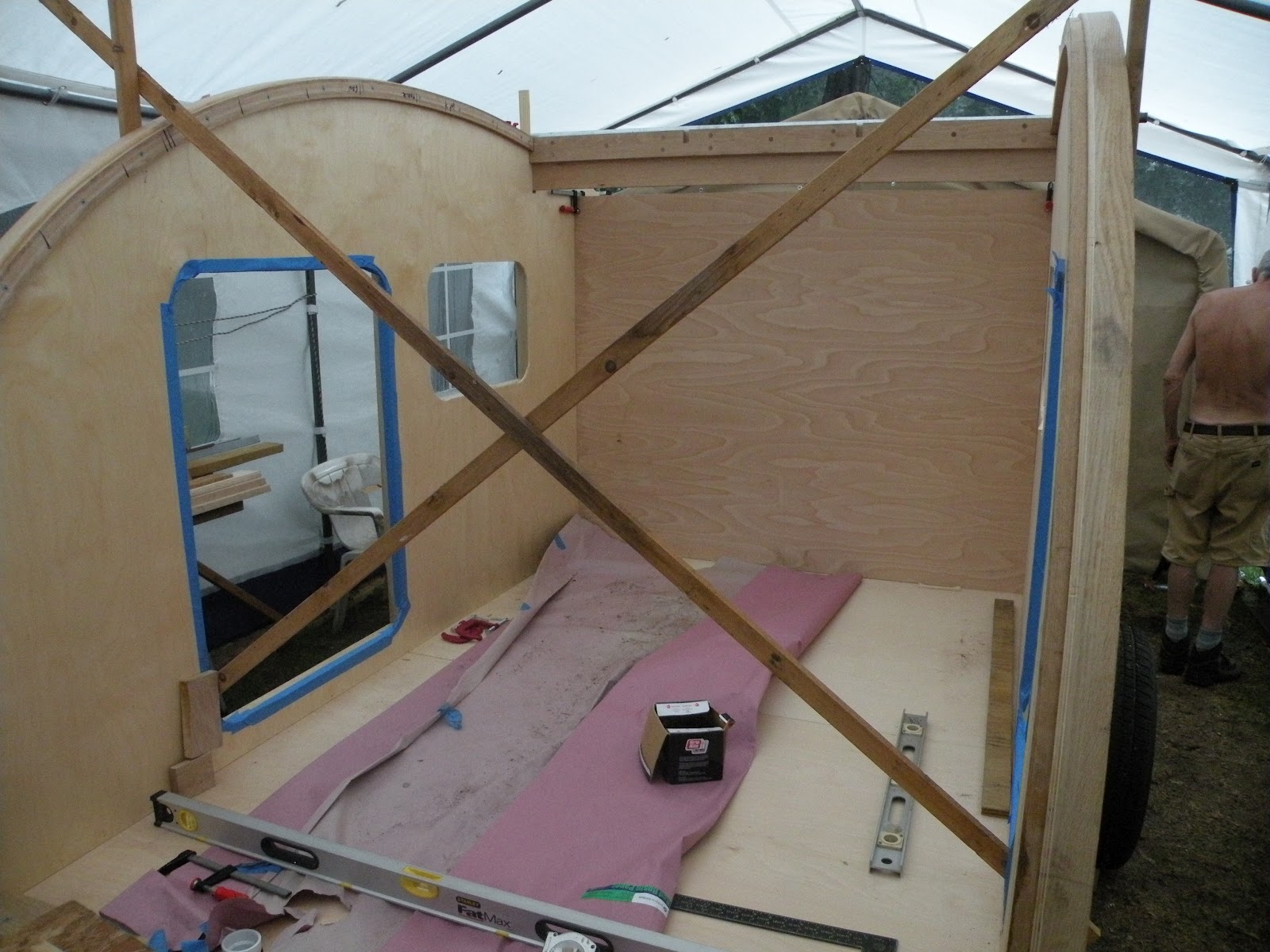
Once that plywood is in place, the next step is to create the basics of the electrical cavity in the front of the cabin so that the wiring process may be started. This cavity will have one horizontal shelf and a top. The front will have two drop-down doors on the top portion and a removable closure on the bottom which will match the doors in detail. The bottom will be made removable instead of hinged for ease of access with a mattress in place.
Below the three cleats are seen rough-fit - the top one will support the top shelf, the middle one will support the internal shelf that will carry the Xantrex, and the one on the floor will back up the face frame.

Below is the face frame, cut but not attached:

 Above is the detail of the main yoke meeting the port side, as seen from the rear.
The main yoke was created when we realized that we didn't have enough 1/4" oak as supplied to laminate ribs long enough to run from the front to the galley partition without embedding ribs formed from two pieces. Since the task of creating two-piece ribs added a layer of complexity that we wished to avoid, the only option was to interrupt the ribs at such a point that our stock could be used to create laminations from one-piece members.
The main yoke consists of three parts - the center piece which runs from side-to-side of the trailer, and intersects the outer and inner ribs, bolting into the verticals supporting the forward part of the main rib, and the forward and aft yokes that receive the outer and inner ribs that are embedded in the roof.
Below is a view, from the rear, of an inner rib both forward and aft of the main yoke.


The galley partition and the forward rib yoke are held in elevation to the top of the internal rib, while the hatch hinge is held to the exterior profile. The plywood sheeting of the front/roof will lie on top of the interior ribs, thereby fitting into the recess created by the hatch hinge as shown above.
Finally, we present a visual: poplar ribbons created by planing the cross-members. This is pure visual fun.


Once that plywood is in place, the next step is to create the basics of the electrical cavity in the front of the cabin so that the wiring process may be started. This cavity will have one horizontal shelf and a top. The front will have two drop-down doors on the top portion and a removable closure on the bottom which will match the doors in detail. The bottom will be made removable instead of hinged for ease of access with a mattress in place.
Below the three cleats are seen rough-fit - the top one will support the top shelf, the middle one will support the internal shelf that will carry the Xantrex, and the one on the floor will back up the face frame.

Below is the face frame, cut but not attached:

The section to the left in the picture will be the top, and will be the electrical cavity. The bottom section will be pure storage.
Both sections will be fronted with 3/4x1-1/4 or so framed door panels. The top panels will be hinged on the bottom and drop down, limited by hardware. The bottom panel (it may be one, it may be two panels, not yet determined) will be a "drop in and latch" approach. With a mattress on the floor, this lower panel will not be able to hinge from the bottom or the top. Since the cavity will represent seldom-accessed storage, the panels covering it will be treated differently - that is, the bottom will key on the face frame and the top will latch. Access to the cavity will require opening the latch and lifting the panel out of position.
I felt that we needed to document some details not shown previously. Thus, the photos below are all details you might have observed, but are presented here with explanations.

The main yoke was created when we realized that we didn't have enough 1/4" oak as supplied to laminate ribs long enough to run from the front to the galley partition without embedding ribs formed from two pieces. Since the task of creating two-piece ribs added a layer of complexity that we wished to avoid, the only option was to interrupt the ribs at such a point that our stock could be used to create laminations from one-piece members.
The main yoke consists of three parts - the center piece which runs from side-to-side of the trailer, and intersects the outer and inner ribs, bolting into the verticals supporting the forward part of the main rib, and the forward and aft yokes that receive the outer and inner ribs that are embedded in the roof.
Below is a view, from the rear, of an inner rib both forward and aft of the main yoke.

Below is a detail of the main yoke, seen from beneath and forward.

Below is a view of the galley partition yoke, from the rear. It, too, is comprised of three layers - working from rear to front we have the hatch hinge mount (3/4" oak), the galley partion (3/4" birch plywood), and the rib yoke (3/4" oak.)

The galley partition and the forward rib yoke are held in elevation to the top of the internal rib, while the hatch hinge is held to the exterior profile. The plywood sheeting of the front/roof will lie on top of the interior ribs, thereby fitting into the recess created by the hatch hinge as shown above.
Finally, we present a visual: poplar ribbons created by planing the cross-members. This is pure visual fun.

2012/08/19
Shaping Up
At our last visit the first piece of interior plywood had been test fitted. Yesterday and today we installed that piece of plywood and created the major cross-members for the front of the trailer. These cross-members embed a 1/4-20 threaded rod from side-to-side to tie the sides and fix the orientation. Here the plywood is permanently installed, and the two lower cross-members have embed threaded rod. The top cross-member is nailed, and picks up the edge of the interior plywood.

Shown below is a detail of the 1/4-20 threaded rod at the side of the trailer:

Each cross-member is notched at one end to accommodate the flexible ducting for running electrical wires.

Shown is a short section of the subduct. DC current will be routed through one subduct, while AC will be routed through another. The pathways thus created will permit pulling wires through the same pathway in the future, should the need arise.
With the inner plywood permanently installed and the threaded-rod cross-members in place, we added cross-members to help fair the outside curve, and to receive the edge of the outer plywood sheathing.


This completes the structure of the front third of the trailer. Next, we can either approach the middle section structure and/or begin construction of the electrical cavity so as to support the wiring process.
2012/08/17
More Progress
It has been several days since the last post, but progress has not stopped. Some additional fitting / preparations were made for the interior ribs. Some millwork was created for the cross-ties that will contain threaded rods, and the non-rodded cross-ties.
Note: we will install 3 or four cross-ties with threaded rod embedded to draw the two sides together consistently. The threaded rods will become obsolete once the inner and outer layers of plywood are installed, but in the interim they will serve a definite purpose.
Meanwhile, we also fed the three 2/0 cables that will run between the battery box and the wiring cavity, carrying the 12v from the batteries to the converter, since doing so now would have been much easier than if the intervening structure was in place.
 As you can see, the tongue box has been removed for this operation.
Next, the two inner ribs were trimmed to length and fit in place.

With those ribs positioned, we filled in the short ribs between the main yoke and the galley paritition.

We then created the millwork for the cross-ties, and laid out the position of the exhaust fan. As the exhaust fan will be positioned centered upon the point where the ellipses meet to as to be positioned not only aesthetically but also on the flattest spot, its position drives the location of the cross-pieces.
That done, we decided to test-fit an interior plywood panel to see how everything was aligning. This required moving the cross-braces to the rear door edge from the front door edge so we could maneuver the plywood into place.

We were pleased with the results, but they showed us where we need to concentrate efforts. For instance, the yoke at the front of the trailer required a doubler to catch the leading edge of the plywood sheet. Also, we need to concentrate cross-pieces in the front part of the curve in order to help the plywood comply.
I took some interior shots, but they were out-of-focus as the camera was not able to use the low-contrast graining of the birch plywood to focus.
Note: we will install 3 or four cross-ties with threaded rod embedded to draw the two sides together consistently. The threaded rods will become obsolete once the inner and outer layers of plywood are installed, but in the interim they will serve a definite purpose.
Meanwhile, we also fed the three 2/0 cables that will run between the battery box and the wiring cavity, carrying the 12v from the batteries to the converter, since doing so now would have been much easier than if the intervening structure was in place.

Next, the two inner ribs were trimmed to length and fit in place.

With those ribs positioned, we filled in the short ribs between the main yoke and the galley paritition.

We then created the millwork for the cross-ties, and laid out the position of the exhaust fan. As the exhaust fan will be positioned centered upon the point where the ellipses meet to as to be positioned not only aesthetically but also on the flattest spot, its position drives the location of the cross-pieces.
That done, we decided to test-fit an interior plywood panel to see how everything was aligning. This required moving the cross-braces to the rear door edge from the front door edge so we could maneuver the plywood into place.

We were pleased with the results, but they showed us where we need to concentrate efforts. For instance, the yoke at the front of the trailer required a doubler to catch the leading edge of the plywood sheet. Also, we need to concentrate cross-pieces in the front part of the curve in order to help the plywood comply.
I took some interior shots, but they were out-of-focus as the camera was not able to use the low-contrast graining of the birch plywood to focus.
2012/08/12
Just Yokin'
The tasks today were to:


 While it may have seemed silly to have created a condition where some ribs are a bit over a foot long, the controlling matter was that the number of milled pieces required to create joint-less ribs (from the front to the galley partition) was more than the number delivered. It was cheaper to create the interim yoke than to have the 1/4" slats supplemented / milled again, at a probable different thickness, and additional cost.
Next, we need to cut the interior ribs to length , anchor them in place and create the cross-pieces that span side-to-side, in some cases 1/4" threaded rid ties.
- Permanently secure the galley partition
- Permanently secure the main yoke
- Permanently affix the minor yoke and main hatch anchor to the galley partition

The above shot shows the main hatch hinge anchor in place.
These views from the rear show the main yoke and the intermediate yoke formed at the galley partition.


Next, we need to cut the interior ribs to length , anchor them in place and create the cross-pieces that span side-to-side, in some cases 1/4" threaded rid ties.
"We're Walking!"
Yesterday, Sean and I took a drive up to Ross Hill Park in Lisbon, CT, where the NE Chapter of the Tear Jerkers were having an annual outing. It was a chance to meet some of the fine people involved, and to see a range of other homebuilts and steal some ideas.
We arrived just before the "trailer crawl" which involves the assembled campers moving from one trailer to the next. The owner of the trailer is asked to give a brief spiel, and the campers are free to inspect the camper, er, trailer, usually inside and out.
I paid particular attention to galley treatments and other details. I was surprised at the number of the trailers that were air conditioned, and the ingenuity involved. If you've been following this blog, you might have noticed no mention of A/C. For now, I'm sticking to that, although I will admit that camping at Ross Hill this weekend, I would have been sticking to just about everything, given the humidity involved.
The title of the post is a reference to the call to action used to get the assembled crowd moving, together, in a pre-determined direction. However, as we proceeded, order broke down, and people might have been gathered around four, five or six different trailers at the same time. That was only to be expected from a group of independent-minded souls having a good time! After all, the Tear Jerkers' motto is "Life moves a little slower on Teardrop time."
I'd like to thank Todd, founder of Tear Jerkers, and all the chapter admins who welcomed us openly, and especially Nancy, the New England chapter's social director, for encouraging us to visit.
Here is a link to the Tear Jerkers home page:
http://www.tearjerkers.net
2012/08/10
Getting Square
Today we marked the internal ribs for length; the fronts were locked, and we used the jig to determine the lengths. That done, the next step was to square up the sides. After clamping / shimming the main yoke into place, we added temporary firring strips to the front edge of the doors in order to square the sides to the platform.
 That accomplished, and with the onset of a torrential downpour, we clamped a temporary shelf onto the fore starboard, which represented high ground.
 What else was there to do but wait out the rain?

2012/08/09
Getting Fit
Today was spent rough fitting the interior ribs to the front yoke.

After fitting the ribs, we secured the front yoke to the platform. Note that the rear of the ribs fit onto a jig designed for the purpose.
Next, we fit the main yoke to the sides:
 Since inserting the main yoke requires spreading the sides, the next steps are:
Stay tuned!

After fitting the ribs, we secured the front yoke to the platform. Note that the rear of the ribs fit onto a jig designed for the purpose.
Next, we fit the main yoke to the sides:

- Remove the main yoke
- Install the rib jig in place of the main yoke
- Fit the two interior ribs, mark their lengths
- Cut the interior ribs
- Remove the jig
- Install the main yoke permanently
- Secure the sides to the platform permanently
- Permanently attach the partition
- Install the interior ribs
Stay tuned!
2012/08/08
Barn Raising
After finalizing some minor details today, we placed the starboard wall, fitted it (where the reflex meets the rear of the trailer) and clamped it into place.
 Next, we stood the galley partition in place to observe the fit between the partition, the wall and the platform.

We removed the partition, fit and stood the port side, clamping it into place.

Again, we placed the partition to observe fit.


There are some minor adjustments to be made to the partition where it meets the deck. After that, we will begin to fit the interior ribs. All the fitting must be accomplished before we begin final assembly. In short, the main yoke spans side-to-side in front of the partition and goes all the way through the walls, bolting into some vertical components of the walls. As it also tucks under the inside ribs that are mounted to the walls, the walls have to be tilted out to insert the yoke. With the yoke in place, we cannot properly fit the inner ribs - for that we have a jig that will be positioned instead of the yoke and permit proper fitting. Once the ribs are fit, the yoke will be installed, then the ribs and the partition.
It was a very good day today. Here is a view from outside the tent that gives a sense of the true, 3-D form. (Note that most of the insulation was removed for convenience and to protect it.)

2012/08/07
Progress Sans Pics
No pics today, but we did accomplish the following:
Tomorrow holds promise.
Oh, and my doctor gave me a physical and pronounced that there are no current conditions to suggest a short(er) life. I'm reminded of a New Yorker cartoon showing the very elderly gentleman, looking very decrepit with skin hanging from his bent-over bones, sitting on the doctor's examining table. The caption has the doctor saying, approximately, "Well, Fred, remember all those healthy things you did earlier in life to add years to your existence? Well, welcome to those years."
- On the platform, cut through the biscuits used in the seams between the sheets. The seams weren't flush owing to either variation in the plywood or variation in the cutting of the biscuit slots. By sawing through the biscuits we have allowed the seams to normalize to the extent they will.
- Trim the rear of the platform plywood to match the 2x6 sides.
- Drill the oak components of the galley partition. These will be assembled in place.
- Trim the rear reflex fill-in on the port side.
Tomorrow holds promise.
Oh, and my doctor gave me a physical and pronounced that there are no current conditions to suggest a short(er) life. I'm reminded of a New Yorker cartoon showing the very elderly gentleman, looking very decrepit with skin hanging from his bent-over bones, sitting on the doctor's examining table. The caption has the doctor saying, approximately, "Well, Fred, remember all those healthy things you did earlier in life to add years to your existence? Well, welcome to those years."
2012/08/06
Heatus Interruptus, Templates and More
The past few days have been quite warm (high 80s to low 90s) and very humid, making the task of getting anything accomplished difficult. I know there are readers who live in more extreme climes, but around these parts, the recent weather has been oppressive.
Before we removed the starboard side from the table, Sean built a template of the actual profile for future use/reference. To do this he cut strips of Masonite (hardboard) and fit them in segments around the curve. Next a second layer was added, alternating the joints. Finally, the segments were glued together using a high-tack adhesive. The perimeter of the layers was clamped, while it was necessary to weight down the field using whatever weights we could find.
Here is a detail shot:
 Note the use of the 6-volt golf cart batteries, which will eventually power the trailer, as well as a 6x6 stood on end as weights.
Here is a panorama created by my Android phone's camera (you can always click a photo to see a larger version) showing a grinder and a couple of buckets with various contents used as weights:
 Finally, here is the template, trimmed to the side profile and held together along the base temporarily, off the table:
 Next we pulled the starboard side off the table and placed the port side. The completed starboard side, standing alongside the base trailer:


 With the port side on the table, we added the inner rib sections and partition cleat, then flipped the side and fit the insulation.

Sean will fill in the reflex at the trailer rear on this side to complete the port side. The remaining tasks before standing walls are to remove the resin paper from the platform, detail the lateral plywood joint that will be in the cabin, add the rib yoke and hinge support to the galley partition, and give the galley partition and main rib yoke a first coat of polyurethane. Tomorrow promises to be less humid for a change!
Before we removed the starboard side from the table, Sean built a template of the actual profile for future use/reference. To do this he cut strips of Masonite (hardboard) and fit them in segments around the curve. Next a second layer was added, alternating the joints. Finally, the segments were glued together using a high-tack adhesive. The perimeter of the layers was clamped, while it was necessary to weight down the field using whatever weights we could find.
Here is a detail shot:

Here is a panorama created by my Android phone's camera (you can always click a photo to see a larger version) showing a grinder and a couple of buckets with various contents used as weights:


Sean will fill in the reflex at the trailer rear on this side to complete the port side. The remaining tasks before standing walls are to remove the resin paper from the platform, detail the lateral plywood joint that will be in the cabin, add the rib yoke and hinge support to the galley partition, and give the galley partition and main rib yoke a first coat of polyurethane. Tomorrow promises to be less humid for a change!
2012/08/02
Starboard Gets Pink!
Today was primarily spent adding rigid foam insulation to the starboard side. (I know that yesterday I said the preparations for the side were complete, but I neglected the foam fill.)
The concept of the structure is that rigid foam fills the cavities between the relatively thin plywood sides, and between the inner and outer ceiling/roof plywood. This creates a sandwich, improving the structure and, as a side consequence, insulating and reducing any drum skin effect of the 1/8" birch plywood on the ceiling. Note: there will be a double layer of the 1/8" birch ply on the front/roof.
We used 3/4" thick rigid foam in two layers for simplicity. Recall from previous posts that some wall cavities are uninterrupted volumes, while others have either a cleat on the inside to support attached shelves/counters, or have a T-shaped vertical member where the inside face is backed by a 2-1/4" wide piece but the outer face only has a 3/4" member.
Using two layers of 3/4" foam allowed us to deal with these vagaries. Further, when we do the curved ceiling, the 3/4" foam will bend much more easily to the profile desired without kerfing.
Here is the completed side:

2012/08/01
Starboard Side Prep
Further preparations to the port side occurred today. We:
There are four "center" ribs, one attached to each side and two in the open area between. Today we fitted and attached the starboard side rib to the side itself.
 These ribs will profile both the interior lining and exterior cladding. As the distance between the outside of the sides is 63+", and the side thickness is 1-3/4" each, the plywood running side-to-side will be approximately 59-5/8". This allows for a clean trim of each interior sheet.
Following is a detail of the rib:

We also attached a cleat for the galley partition:
 Finally, Sean filled in the section at the rear below the platform with a scrap cut off from one of the ribs:
 With these additions, the preparation of the port side are essentially complete.
- Sized and attached the roof rib to the side
- Filled in the aft reflex section
- Attached the galley partition cleat to the side
There are four "center" ribs, one attached to each side and two in the open area between. Today we fitted and attached the starboard side rib to the side itself.

Following is a detail of the rib:

We also attached a cleat for the galley partition:


Subscribe to:
Posts (Atom)