Yesterday we cut and dry-fit the main cross beam and yoke assembly. When I arrived today, Sean had fitted it up with this combination of clamps and jigs:
This arrangement brought all three pieces of oak into proper alignment. We used it for pre-drilling and setting the 2" wood screws from this side. Once that task was accomplished we flipped it around and repeated the process, but with counter-bores designed to receive oak plugs.
View from the aft side, which will be concealed:
View from the forward side, which will be exposed:
Detail of the plugged forward side:
The balance of the day's work was aimed at the galley partition. The main sheet of plywood was cut yesterday, but today we needed to cut an extension (48 inches to 51-1/2 inches) Further, we needed to cut the yoke on the forward side of the partition that will receive ribs, and the aft board that will consist of the galley hinge mounting point.
The finished pieces are shown below:
The plywood piece shown will extend the 48" plywood partition to 51.5". The solid, non-notched oak piece will be the aft-of-partition galley hinge mount. The notched piece of oak on the right will be the rib yoke forward of the galley partition. The notched piece on the left will be mounted at the front of the platform to receive the ribs.
Next step: Build up the galley partition, fit the outside ribs to the wall structures.
2012/07/31
2012/07/30
Progress 7/30
Today was another day of excellent progress. We:
This photo shows the notches to receive one of the interior ribs. Note that the two yokes and the main beam have not yet been aligned vertically in this shot.
This is the starboard end of the assembly.
This yoke assembly will be a key component in the overall structure of the cabin, working with the galley partition to provide lateral rigidity. The next step is to pre-drill for the screws that will unite the three pieces, then glue and affix them together with screws.
- Cut the galley partition
- Routed a rabbet into the galley partition to receive the galley countertop
- Sorted through the front rib halves to pick out the two best, to be used as interior ribs
- Cut the three pieces for the main yoke, which will run from side-to-side in front of the galley partition and receive ribs from the front and the rear
The yoke consists of three pieces as shown above. The main beam is the center piece. It acts as a flange that will run through both walls and be bolted into them. On either side of that main beam is a yoke, notched to receive the various ribs, which will be interrupted at the yoke. The tops of the three boards are beveled to match the curvature of the roof where the yoke will be installed.
This is a closeup of the port side end. The trailer front is to the left. The front rib that is attached to the port wall will key into the notch on the left, while the short rib that runs between the yoke and the galley opening will key into the notch on the right. The rib sections in question will only be as thick as the notch shown. The balance of the main beam will protrude through the wall in the cutout seen in the photos of the walls in the previous post.
This is the starboard end of the assembly.
This yoke assembly will be a key component in the overall structure of the cabin, working with the galley partition to provide lateral rigidity. The next step is to pre-drill for the screws that will unite the three pieces, then glue and affix them together with screws.
2012/07/29
Both Sides Receive First Coat of Polyurethane!
Today the trailer port side was moved onto the trailer bed after the bed was covered with rosin paper (typically used in construction to provide a slip between a hardwood floor and the subfloor.) In this case we simply wanted to protect the deck from what we might place upon it, as in one of the sides.
The starboard side was placed on the work table, where we installed the necessary additional backers. We then flipped it over and cut out the door and window openings, as well as the channel for the yoke header.
Both sides were sanded with 150 grit paper, and given a first coat of polyurethane.
The port side wall is on the trailer, while the starboard is on the work table:
The starboard side was placed on the work table, where we installed the necessary additional backers. We then flipped it over and cut out the door and window openings, as well as the channel for the yoke header.
Both sides were sanded with 150 grit paper, and given a first coat of polyurethane.
The port side wall is on the trailer, while the starboard is on the work table:
Tomorrow we will approach the galley partition, the main rib yoke, and getting the platform coated with polyurethane.
2012/07/28
Side Prep
The next step in the process is to get each side properly prepped to be mounted onto the platform. To do this, some additional "backers" were required in the side wall:
Above is the horizontal backer for the galley counter top cleat, added today.
Above is the port side provision for a shore connection.
Next we cut out the window and door openings. A 6" hole saw was used for the corners, while the sides were cut with a router and a flush trim bit.
The trim rings are interior, which matches with the image above,since this is the port side interior wall. The view below shows the installed window and door, assuming the starboard side:
The hole in the foreground is for the shore connection, which will actually penetrate the interior wall.
The slot shown below will receive the 4/4 oak crossmember, to which the rib yokes will be attached (and run between the inner wall surfaces.)
The next step for this side is to sand and apply a sealer coat of polyurethane.
Above is the horizontal backer for the galley counter top cleat, added today.
Above is the port side provision for a shore connection.
Next we cut out the window and door openings. A 6" hole saw was used for the corners, while the sides were cut with a router and a flush trim bit.
The trim rings are interior, which matches with the image above,since this is the port side interior wall. The view below shows the installed window and door, assuming the starboard side:
The hole in the foreground is for the shore connection, which will actually penetrate the interior wall.
The slot shown below will receive the 4/4 oak crossmember, to which the rib yokes will be attached (and run between the inner wall surfaces.)
The next step for this side is to sand and apply a sealer coat of polyurethane.
2012/07/27
Side Wall Consistency and Refinement
With the platform complete, our attention turned to the side walls. The first task was to affix them to each other and, using a special flush trim bit, trim them to each other to assure a consistent profile curve.
To accomplish this we screwed the two sides to each other. I used a bit from Rockler, that is a 2" long, 1/2" shank carbide cutter with both top and bottom bearings of differing diameters, to trim the top side to the bottom side (where the top side extended beyond the bottom with a bottom bearing the same size as the cutter.) Next, we flipped the assembly and repeated the process.
Next we removed the starboard side and left the port side on the table. We added some cleats aft for the galley counter top:
The mark above is the centerline of the shore power connector. A reference hole has been driven through the inside plywood to indicate the center position of the connector for future reference.
After all such details are located we will flip the side and rout open the door and window, prepare the side to receive the oak rib yoke assembly, and pre-drill the holes through the sills for the screws that will attach the sides to the platform.
To accomplish this we screwed the two sides to each other. I used a bit from Rockler, that is a 2" long, 1/2" shank carbide cutter with both top and bottom bearings of differing diameters, to trim the top side to the bottom side (where the top side extended beyond the bottom with a bottom bearing the same size as the cutter.) Next, we flipped the assembly and repeated the process.
Next we removed the starboard side and left the port side on the table. We added some cleats aft for the galley counter top:
Next we added some cleats forward for the electrical cavity. Part of this task for the port side was to accommodate the shore power connector.
The mark above is the centerline of the shore power connector. A reference hole has been driven through the inside plywood to indicate the center position of the connector for future reference.
After all such details are located we will flip the side and rout open the door and window, prepare the side to receive the oak rib yoke assembly, and pre-drill the holes through the sills for the screws that will attach the sides to the platform.
2012/07/26
A Milestone Day
Today was definitely a milestone day. To start, we added the sides to the party tent under which the trailer is being assembled in order to protect the trailer from rain. Next, we leveled the trailer so that the basic construction is conducted from a position of level.
Next, we cemented the ell for the clearance light feed:
We will tap into the right rear tail light and connect to the clearance light feed, route it to the rear inside plastic sub-ducting, then feed it up into this fitting and then into the open end of the wye seen forward, and finally, up into a cavity inside the hatch. From there the clearance light feed will go to the front and rear left and right side clearance lights.
The view below shows the trailer base ready for the deck:
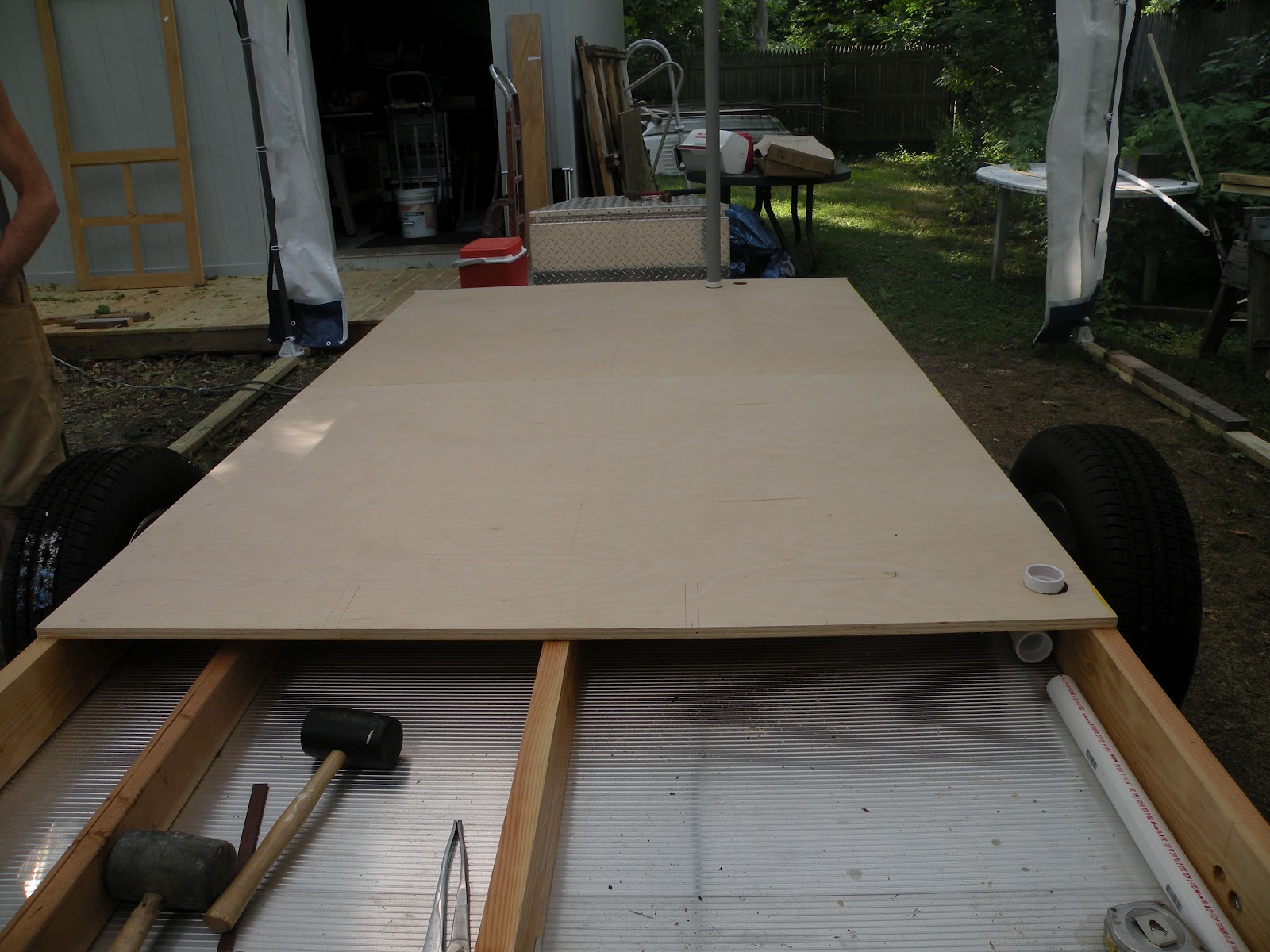
We started affixing the deck plywood from the front:
Next we applied the center and the aft pieces. Each piece was glued down and screwed to the 2x6 frame. The pieces were joined with biscuits.
With the deck fully attached, the next steps are to fair the two sides to each other (to assure a common profile), trim the rear portions of the laminations to fit the trailer, prepare the galley partition, then affix one side, the galley partition, then the other side.
Stay tuned!
Next, we cemented the ell for the clearance light feed:
We will tap into the right rear tail light and connect to the clearance light feed, route it to the rear inside plastic sub-ducting, then feed it up into this fitting and then into the open end of the wye seen forward, and finally, up into a cavity inside the hatch. From there the clearance light feed will go to the front and rear left and right side clearance lights.
The view below shows the trailer base ready for the deck:
We started affixing the deck plywood from the front:
Next we applied the center and the aft pieces. Each piece was glued down and screwed to the 2x6 frame. The pieces were joined with biscuits.
With the deck fully attached, the next steps are to fair the two sides to each other (to assure a common profile), trim the rear portions of the laminations to fit the trailer, prepare the galley partition, then affix one side, the galley partition, then the other side.
Stay tuned!
2012/07/24
Electrical Routing, and the Deck
Today we worked on the conduit that will carry the wiring between the battery (tongue) box and the cavity in the front of the cab where all the connections will be made, and the conduit that will carry both 120v and 12v distribution from the front to the rear.
Refer back to the previous post to see the connection between the battery box and the trailer body. Sean made some washers to help flatten the gaskets against the aluminum, in particular the diamond plate of the battery box. We permanently affixed the connection at the trailer's front edge and installed an ell rather than the sweep shown previously.
Next we ran a conduit along the starboard side from a point just behind the galley partition to the front, then laterally to the same general area as the tongue box conduit. This pipe will carry some 3/8" "sub-ducting" or corrugated plastic tubing, within which we will run either the 120v or the 12v wires back to the galley partition.
In the view above you see the longitudinal pipe terminating in a wye - a pluming term for a y-shaped part. A "street" 45 turns the run to the vertical. This penetration will be just behind the galley partition. Three sub-ducts will be installed - one for AC, one for DC, and one spare. The open end of the wye will permit convenient access as required, and will accommodate a feed from the trailer rear for a clearance light circuit.
This view shows the head end of the trailer and the two turns to the vertical that will penetrate up into the interior wiring cavity. Again, note that for the battery box connection we have switched to a standard ell from the previously shown sweep. The sweep has been deployed on the aftward run .
This view shows the front two platform panels with holes fit into them for the penetrations.
Tomorrow we will pre-drill through the plywood then screw it to the structure, completing the platform.
Refer back to the previous post to see the connection between the battery box and the trailer body. Sean made some washers to help flatten the gaskets against the aluminum, in particular the diamond plate of the battery box. We permanently affixed the connection at the trailer's front edge and installed an ell rather than the sweep shown previously.
Next we ran a conduit along the starboard side from a point just behind the galley partition to the front, then laterally to the same general area as the tongue box conduit. This pipe will carry some 3/8" "sub-ducting" or corrugated plastic tubing, within which we will run either the 120v or the 12v wires back to the galley partition.
In the view above you see the longitudinal pipe terminating in a wye - a pluming term for a y-shaped part. A "street" 45 turns the run to the vertical. This penetration will be just behind the galley partition. Three sub-ducts will be installed - one for AC, one for DC, and one spare. The open end of the wye will permit convenient access as required, and will accommodate a feed from the trailer rear for a clearance light circuit.
This view shows the head end of the trailer and the two turns to the vertical that will penetrate up into the interior wiring cavity. Again, note that for the battery box connection we have switched to a standard ell from the previously shown sweep. The sweep has been deployed on the aftward run .
This view shows the front two platform panels with holes fit into them for the penetrations.
Tomorrow we will pre-drill through the plywood then screw it to the structure, completing the platform.
Subscribe to:
Posts (Atom)